Technical Data for Cap Size & Closures
The closure industry has no standardized dimensions to the extent that the container industry has, and it is usually advantageous to buy both containers and closures from the same supplier when possible.
Similar to the container industry, when a closure finish is designated as 33-400, it means that the nominal diameter measured across the inside of the cap at the opening is approximately 33mm. (See “T” dimension on illustration.) The 400 designates a specific style of thread.

The thread finish of the cap and container must be the same. A container with a 33-400 thread finish should be used with a cap with a 33-400 thread finish.
Table Instructions
Cap Size Determination
To determine the cap size, measure the cap opening from one side of the inner wall to the opposite side of the inner wall. Compare this number to the numbers found in the “T” dimension columns in Table 1a or 1b. Once this number is found in the table, follow the row to the far left to find the “Nominal Diameter” of the cap.
Thread Size Determination
To determine the specific style of thread, measure the depth of the cap from the liner surface to the outside edge of the cap. Compare this number to the numbers found in the “H” dimension columns in Table 1a or 1b that appear in the same row as the Nominal Diameter of the cap. Once this number is found in the table, follow the column to the top to find the specific style number (400 in the above example).
Dimensions
The table sizes are close, but may not be exact due to liner thickness. They can still help you find the right cap size.
Suggested Torque for Screw Caps
The integrity of the cap-to-container seal depends upon a number of variables, such as the materials of the cap, liner, and container, the sealing surface of the container, and the application torque applied to the closure. The most important of these is the application torque. The contents could leak if the cap is applied too loosely, especially during shipping. If the cap is applied too tightly, it may be too difficult to remove, or the container could break during application.
Other Notes
Table 2 offers some suggested torques that should adequately seal most applications. It is recommended that proper tests be performed to determine the optimum torque for the application.
The most practical way to check the tightness is to measure the removal torque after the cap has been on the container for about 5 minutes. The removal torque should closely approximate the application torque. The minimum removal torque noted in the table should be maintained after a 24-hour period.
Table 1a. Cap Thread Finish Dimensions (Dimensions are in inches)
| 400 | 410 | 415 | 425 | 430 | ||||||
| Nominal Dia (mm) |
T | H | T | H | T | H | T | H | T | H |
|---|---|---|---|---|---|---|---|---|---|---|
| 8 | -- | -- | -- | -- | -- | -- | 0.360 | 0.245 | -- | -- |
| 10 | -- | -- | -- | -- | -- | -- | 0.415 | 0.255 | -- | -- |
| 13 | -- | -- | -- | -- | 0.520 | 0.430 | 0.520 | 0.280 | -- | -- |
| 15 | -- | -- | -- | -- | 0.585 | 0.535 | 0.585 | 0.280 | -- | -- |
| 18 | 0.790 | 0.360 | 0.710 | 0.500 | 0.710 | 0.595 | -- | -- | 0.710 | 0.605 |
| 20 | 0.790 | 0.360 | 0.790 | 0.530 | 0.790 | 0.720 | -- | -- | 0.790 | 0.605 |
| 22 | 0.870 | 0.360 | 0.870 | 0.560 | 0.870 | 0.815 | -- | -- | 0.870 | 0.605 |
| 24 | 0.945 | 0.390 | 0.945 | 0.620 | 0.945 | 0.935 | -- | -- | 0.945 | 0.650 |
| 28 | 1.095 | 0.390 | 1.095 | 0.685 | 1.095 | 1.060 | -- | -- | 1.095 | 0.725 |
| 30 | 1.130 | 0.390 | -- | -- | -- | -- | -- | -- | 1.130 | 0.760 |
| 33 | 1.270 | 0.390 | -- | -- | -- | -- | -- | -- | 1.270 | 0.775 |
| 35 | 1.370 | 0.390 | -- | -- | -- | -- | -- | -- | -- | -- |
| 38 | 1.480 | 0.390 | -- | -- | -- | -- | -- | -- | 1.480 | 0.940 |
| 40 | 1.590 | 0.390 | -- | -- | -- | -- | -- | -- | -- | -- |
| 43 | 1.660 | 0.390 | -- | -- | -- | -- | -- | -- | -- | -- |
| 45 | 1.750 | 0.390 | -- | -- | -- | -- | -- | -- | -- | -- |
| 48 | 1.850 | 0.390 | -- | -- | -- | -- | -- | -- | -- | -- |
| 51 | 1.975 | 0.390 | -- | -- | -- | -- | -- | -- | -- | -- |
| 53 | 2.075 | 0.390 | -- | -- | -- | -- | -- | -- | -- | -- |
| 58 | 2.230 | 0.390 | -- | -- | -- | -- | -- | -- | -- | -- |
| 60 | 2.235 | 0.390 | -- | -- | -- | -- | -- | -- | -- | -- |
| 63 | 2.470 | 0.390 | -- | -- | -- | -- | -- | -- | -- | -- |
| 66 | 2.585 | 0.390 | -- | -- | -- | -- | -- | -- | -- | -- |
| 70 | 2.745 | 0.390 | -- | -- | -- | -- | -- | -- | -- | -- |
| 75 | 2.920 | 0.390 | -- | -- | -- | -- | -- | -- | -- | -- |
| 77 | 3.040 | 0.470 | -- | -- | -- | -- | -- | -- | -- | -- |
| 83 | 3.275 | 0.470 | -- | -- | -- | -- | -- | -- | -- | -- |
| 89 | 3.520 | 0.515 | -- | -- | -- | -- | -- | -- | -- | -- |
| 100 | 3.945 | 0.580 | -- | -- | -- | -- | -- | -- | -- | -- |
| 110 | 4.340 | 0.580 | -- | -- | -- | -- | -- | -- | -- | -- |
| 120 | 4.735 | 0.675 | -- | -- | -- | -- | -- | -- | -- | -- |
Table 1b. Cap Thread Finish Dimensions (Dimensions are in millimeters)
| 400 | 410 | 415 | 425 | 430 | ||||||
| Nominal Dia (mm) |
T | H | T | H | T | H | T | H | T | H |
|---|---|---|---|---|---|---|---|---|---|---|
| 8 | -- | -- | -- | -- | -- | -- | 9.14 | 6.22 | -- | -- |
| 10 | -- | -- | -- | -- | -- | -- | 10.54 | 6.48 | -- | -- |
| 13 | -- | -- | -- | -- | 13.21 | 10.92 | 13.21 | 7.11 | -- | -- |
| 15 | -- | -- | -- | -- | 14.86 | 13.59 | 14.86 | 7.11 | -- | -- |
| 18 | 18.03 | 9.14 | 18.03 | 12.70 | 18.03 | 15.11 | -- | -- | 18.03 | 15.37 |
| 20 | 20.07 | 9.14 | 20.07 | 13.46 | 20.07 | 18.29 | -- | -- | 20.07 | 15.37 |
| 22 | 22.10 | 9.14 | 22.10 | 14.22 | 22.10 | 020.70 | -- | -- | 22.10 | 15.37 |
| 24 | 24.00 | 9.91 | 24.00 | 15.75 | 24.00 | 23.75 | -- | -- | 24.00 | 16.51 |
| 28 | 27.81 | 9.91 | 27.81 | 17.40 | 27.81 | 26.92 | -- | -- | 27.81 | 18.42 |
| 30 | 28.70 | 9.91 | -- | -- | -- | -- | -- | -- | 28.70 | 19.30 |
| 33 | 32.26 | 9.91 | -- | -- | -- | -- | -- | -- | 32.26 | 19.69 |
| 35 | 34.80 | 9.91 | -- | -- | -- | -- | -- | -- | -- | -- |
| 38 | 37.59 | 9.91 | -- | -- | -- | -- | -- | -- | 37.59 | 23.88 |
| 40 | 40.39 | 9.91 | -- | -- | -- | -- | -- | -- | -- | -- |
| 43 | 42.16 | 9.91 | -- | -- | -- | -- | -- | -- | -- | -- |
| 45 | 44.45 | 9.91 | -- | -- | -- | -- | -- | -- | -- | -- |
| 48 | 47.63 | 9.91 | -- | -- | -- | -- | -- | -- | -- | -- |
| 51 | 50.16 | 9.91 | -- | -- | -- | -- | -- | -- | -- | -- |
| 53 | 52.71 | 9.91 | -- | -- | -- | -- | -- | -- | -- | -- |
| 58 | 56.64 | 9.91 | -- | -- | -- | -- | -- | -- | -- | -- |
| 60 | 59.69 | 9.91 | -- | -- | -- | -- | -- | -- | -- | -- |
| 63 | 62.74 | 9.91 | -- | -- | -- | -- | -- | -- | -- | -- |
| 66 | 65.53 | 9.91 | -- | -- | -- | -- | -- | -- | -- | -- |
| 70 | 69.72 | 9.91 | -- | -- | -- | -- | -- | -- | -- | -- |
| 75 | 74.17 | 9.91 | -- | -- | -- | -- | -- | -- | -- | -- |
| 77 | 77.22 | 11.94 | -- | -- | -- | -- | -- | -- | -- | -- |
| 83 | 83.19 | 11.94 | -- | -- | -- | -- | -- | -- | -- | -- |
| 89 | 89.41 | 13.08 | -- | -- | -- | -- | -- | -- | -- | -- |
| 100 | 100.20 | 14.73 | -- | -- | -- | -- | -- | -- | -- | -- |
| 110 | 110.23 | 14.73 | -- | -- | -- | -- | -- | -- | -- | -- |
| 120 | 120.27 | 17.14 | -- | -- | -- | -- | -- | -- | -- | -- |
| Material | Description | Applications |
| Poly-Vinyl | One mil poly vinyl fi lm bonded to one mil HDPE on a #30 white pulp paper backing. Superior to plain pulp paper because it provides excellent moisture barrier. |
General purpose: Suitable for wide range of applications. Chemical resistance: Good for mild acids, alkalis, solvents, alcohols, oils and aqueous products; poor for active hydrocarbons and bleaches. |
|---|---|---|
| Poly-Seal® | Manufactured from LDPE. The unique cone design provides a wedge type seal that not only seals across the top but also across the inside diameter. |
Unique problem solving type of liner. This liner is stress crack resistant and offers superior torque retention and excellent sealing characteristics. It is recommended that this liner be tested prior to use for leak seal. |
| Foamed Polyethylene | A one piece, three ply coextruded liner consisting of foamed and solid LDPE. The foam core is sandwiched with solid clear PE. |
General Purpose: Broad applications base. Chemical resistance-good for acids, alkalis, solvents, alcohols, oils, household cosmetics and aqueous products. Poor for hydrocarbon solvents. Liner provides tight seal. |
| Pulp/Metal Foil | Aluminum foil bonded to pulp board. | Good barrier properties, good resistance to hydrocarbons, oils, ketones and alcohols. Not good for acids or alkalis. |
| Styrene-Butadiene Rubber (14B) |
The white rubber lining material consists of homogeneous sulfur cured styrene-butadiene rubber (SBR). FDA Status complies with 21CFR 177.26, “Rubber articles intended for repeated use.” |
Excellent properties of resilience, resistant to moisture vapor. Satisfactory for most moderate chemicals. Not good for oils, strong acids and hydrocarbons. Autoclavable. |
| Styrene-Butadiene Rubber/0.005 PTFE |
The white rubber/0.005” PTFE liner consists of virgin PTFE bonded to the white sulfur cured, styrene-butadiene rubber. Complies with the FDA 21CFR 177.1550. |
Designed for the ultimate in product safety. PTFE provides totally inert inner seal and surface facing the sample or product. Autoclavable. |
| PTFE Faced Silicone Rubber |
The white rubber/0.005” PTFE liner consists of virgin PTFE bonded to the white sulfur cured, styrene-butadiene rubber. Complies with the FDA 21CFR 177.1550. |
Designed for the ultimate in product safety. PTFE provides totally inert inner seal and surface facing the sample or product. Autoclavable. |
| PTFE Faced Foamed Polyethylene |
The liner consists of 0.005” thick PTFE bonded to 0.055” thick silicone rubber. |
Ideal for low temperature storage applications. PTFE facing provides excellent chemical barrier. Autoclavable |
Table 2. Suggested Torques for Closures (in-lb)
| Phenolic/Urea Cap on Glass Container |
Phenolic/Urea Cap on Plastic Container |
PP/PE Cap on Glass Container |
PP/PE Cap on Plastic Container |
|||||
| Cap mm |
Application Torque |
Min Removal Torque |
Application Torque |
Min Removal Torque |
Application Torque |
Min Removal Torque |
Application Torque |
Min Removal Torque |
|---|---|---|---|---|---|---|---|---|
| 15 | 8 | 4 | 6 | 3 | 12 | 7 | 8 | 4 |
| 18 | 9 | 5 | 7 | 4 | 13 | 8 | 9 | 5 |
| 20 | 10 | 5 | 8 | 4 | 15 | 9 | 10 | 5 |
| 22 | 11 | 6 | 9 | 5 | 17 | 10 | 11 | 5 |
| 24 | 12 | 6 | 10 | 5 | 18 | 11 | 12 | 6 |
| 28 | 14 | 7 | 12 | 6 | 21 | 12 | 14 | 7 |
| 33 | 18 | 9 | 15 | 7 | 24 | 14 | 17 | 8 |
| 38 | 20 | 10 | 17 | 7 | 29 | 17 | 19 | 9 |
| 43 | 22 | 11 | 18 | 9 | 33 | 20 | 22 | 11 |
| 48 | 24 | 12 | 20 | 10 | 36 | 22 | 24 | 12 |
| 58 | 28 | 14 | 24 | 12 | 44 | 26 | 29 | 14 |
| 70 | 35 | 18 | 28 | 14 | 52 | 32 | 35 | 17 |
| 89 | 45 | 22 | 36 | 18 | 65 | 40 | 45 | 22 |
| 100 | 50 | 25 | 40 | 20 | 75 | 38 | 50 | 25 |
Note: Closures and liners are designed for a variety of applications. Product performance can vary depending on conditions. It is recommended that proper tests be performed to determine the best liner for the application.
Related Products
-
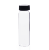
![KIMBLE® Screw Thread Sample Vials with Attached Closures]() KIMBLE® Screw Thread Sample Vials with Attached Closures
KIMBLE® Screw Thread Sample Vials with Attached ClosuresStarting at $121.62
-
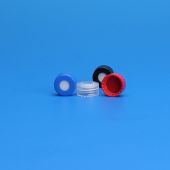
![13-425mm, Septa for Screw Thread Closures]()